
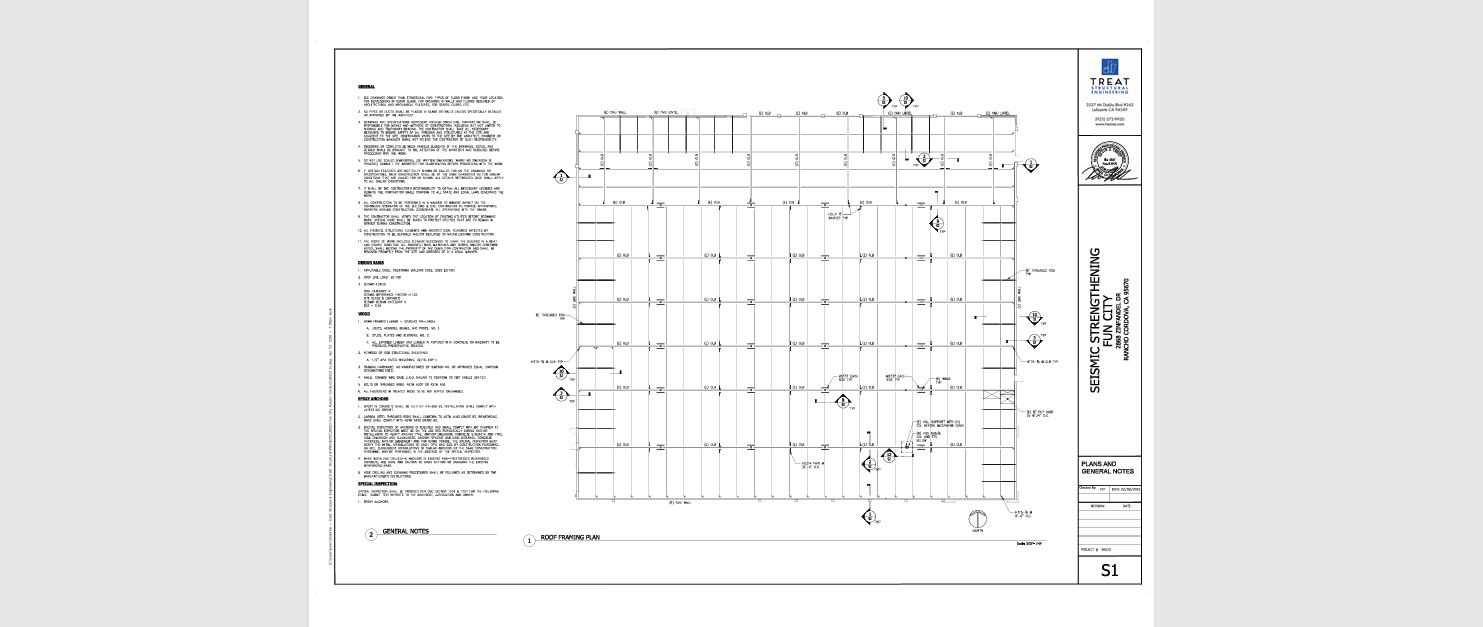
This estimate review was prepared for the concrete scope associated with the structural drawing package dated 04/03/2026 for the commercial project located at 2868 Zinfandel Drive, Rancho Cordova, California.
The drawing set reviewed consists primarily of structural Sheets S1 and S2 prepared by Treat Engineering. Although the package is heavily focused on roof framing and structural wood support conditions, sufficient structural references were available to establish preliminary concrete scope assumptions tied to foundation support, bearing conditions, and slab-related structural coordination.
The building appears to utilize conventional slab-on-grade construction supporting wood-framed roof structure with glulam beam bearing conditions and perimeter structural wall support.
Structural references affecting the concrete package were reviewed primarily from framing support relationships shown on S1 and supporting structural sections and attachment details shown on S2.
Because the uploaded set is not a full civil or foundation package, the estimate was developed as a subcontractor bid-level budgeting exercise using standard commercial concrete assumptions consistent with the structural framing layout shown.
Scope Breakdown
The concrete scope was carried as a conventional light commercial structural concrete package associated with the building footprint shown in the structural drawings.
Primary concrete scope included:
- Building slab-on-grade placement
- Continuous perimeter footings
- Interior isolated pad footings
- Thickened slab conditions
- Reinforcing steel associated with structural concrete
- Vapor barrier below slab
- Aggregate base preparation allowance
- Anchor bolt placement coordination
- Concrete finishing and curing
Secondary scope items included:
- Slab edge formwork
- Equipment pads reasonably implied by structural coordination
- Minor housekeeping pads
- Reinforcing accessories and chairs
- Sawcut control joints
The estimate excluded:
- Site concrete beyond building footprint
- ADA flatwork
- Exterior paving
- Underground utilities
- Shoring systems
- Dewatering
- Structural steel embed fabrication
- Architectural polished concrete finishes
Only concrete work reasonably implied from the structural package and commercial building layout was carried.
Drawing Review Process
The review began with S1 to establish the overall building footprint and structural bearing layout. Roof framing relationships and beam support conditions help determine probable load transfer locations and foundation intensity.
Although explicit footing schedules and slab details are limited within the uploaded package, perimeter bearing relationships and beam locations shown on the framing plan provided sufficient information to establish preliminary footing assumptions.
Support conditions shown throughout S2 were reviewed to understand probable concentrated loading areas requiring isolated foundations or thickened slab conditions.
Because the structural set provided is incomplete from a foundation-design standpoint, several assumptions were required regarding slab thickness, footing dimensions, reinforcing schedules, and subgrade preparation.
Typical Northern California commercial slab construction practices were used where exact foundation details were not explicitly shown.
No geotechnical report was included in the uploaded documents. As a result, subgrade stabilization, over-excavation requirements, and soil export/import costs were excluded from the base estimate.
The estimate was therefore developed as a realistic subcontractor budgeting exercise rather than a final structural concrete buyout.
Quantity Takeoff Methodology
Concrete quantities were developed using the building footprint derived from the structural framing plan on S1.
The slab-on-grade area was measured using the overall structural footprint, with adjustments made for recessed framing zones and perimeter offsets.
Continuous footing quantities were developed using perimeter wall lengths and assumed footing dimensions consistent with light commercial wood-framed construction in California.
Interior pad footings were carried proportionally based on glulam beam support conditions and concentrated bearing locations visible within the framing plan.
Concrete volume calculations were developed using standard estimating conventions:
- Slab measured in square feet and converted to cubic yards based on assumed slab thickness
- Continuous footings measured centerline-to-centerline
- Isolated footings measured individually by assumed footing dimensions
- Reinforcing carried proportionally by concrete volume and footing density
Waste factors used during quantity development:
- Concrete overage: approximately 5%
- Reinforcing steel: approximately 8%
- Vapor barrier and base material: approximately 5%
Sawcut control joints were carried proportionally against slab geometry and assumed joint spacing typical for commercial slab placement.
No elevated slab conditions were identified within the uploaded structural package.
Material Takeoff
Slab-on-Grade Concrete
Primary slab quantities were developed from the structural building footprint shown on S1.
- Estimated slab footprint: approximately 8,100 SF
- Assumed slab thickness: 5 inches
- Net concrete volume: approximately 125 CY
- Overage applied: 5%
- Final slab concrete quantity: approximately 131 CY
Includes standard slab placement allowance and minor thickened slab transitions.
Continuous Perimeter Footings
Perimeter footing quantities were developed using overall structural perimeter dimensions.
- Estimated footing length: approximately 430 LF
- Assumed footing size: 24 inches wide x 12 inches deep
- Final footing concrete quantity: approximately 32 CY
Includes continuous perimeter support and localized reinforcing thickening assumptions.
Interior Pad Footings
Pad footing quantities were carried at major beam bearing locations implied from the framing layout.
- Estimated isolated footing count: 9 EA
- Average assumed footing size: 4 feet x 4 feet x 18 inches
- Final pad footing quantity: approximately 8 CY
Reinforcing Steel
Reinforcing quantities were carried proportionally against slab and footing volume.
- Estimated reinforcing quantity: approximately 11,800 LB
Includes slab reinforcing, footing bars, dowels, laps, and standard commercial placement waste.
Vapor Barrier and Aggregate Base
Below-slab support materials were carried against the full slab footprint.
- Vapor barrier quantity: approximately 8,500 SF
- Aggregate base allowance: approximately 75 CY
Formwork and Accessories
Formwork quantities were developed from slab edge and footing perimeter conditions.
Included accessories:
- Form lumber
- Stakes and braces
- Control joint materials
- Rebar chairs and supports
- Anchor bolt coordination allowance
- Cure and seal materials
Labor & Costing Logic
Labor productivity assumptions were based on a conventional commercial concrete crew performing slab and footing work over prepared subgrade.
The building geometry remains relatively efficient overall, allowing favorable placement productivity compared to heavily segmented commercial structures.
Labor build-up included:
- Layout and excavation coordination
- Formwork installation
- Reinforcing placement
- Concrete placement and finishing
- Sawcutting and curing
- Cleanup and demobilization
Material pricing assumptions reflected current Northern California market conditions for:
- Ready-mix concrete
- Reinforcing steel
- Vapor barrier materials
- Form lumber
- Aggregate base
- Concrete accessories and consumables
California labor burden and trucking exposure were incorporated into the pricing structure.
Equipment assumptions included:
- Skid steer support
- Plate compactor and small equipment
- Concrete pump allowance
- Power trowels and sawcut equipment
- General placement support equipment
Estimated productivity assumptions used during pricing:
- Slab placement: approximately 900 to 1,200 SF per crew day depending on finish requirements
- Reinforcing placement carried separately due to footing density
- Formwork productivity adjusted for perimeter geometry and footing transitions
No specialty architectural finish requirements were identified within the uploaded structural package.
Final Bid Summary
| Cost Component | Estimated Value |
|---|---|
| Material Cost | $72,500 |
| Labor Cost | $58,900 |
| Equipment & Handling | $14,200 |
| Subtotal | $145,600 |
| Overhead & Profit | $21,800 |
| Final Bid Total | $167,400 |
Pricing reflects commercial concrete market conditions for the Rancho Cordova region at the time of estimate preparation.
Estimator Commentary
The overall concrete package is relatively manageable from a production standpoint due to the straightforward building geometry and conventional slab-on-grade construction assumptions.
The largest pricing variables remain foundation design confirmation and final geotechnical requirements since the uploaded structural package does not include a complete footing schedule or soils report.
If geotechnical recommendations later require over-excavation, import fill, or subgrade stabilization, costs could increase materially beyond the current estimate.
Another variable affecting pricing is final reinforcing density. The current estimate assumes standard light-commercial reinforcing schedules consistent with the framing loads shown. Final structural engineering revisions could increase reinforcing quantities depending on seismic requirements and final footing sizing.
Concrete pricing in Northern California continues to remain sensitive to ready-mix trucking rates, fuel costs, and labor availability. Pumping duration and site access could also affect final subcontractor pricing depending on field logistics.
No elevated structural slabs or unusually complex concrete geometry were identified within the reviewed package, which helps maintain efficient placement productivity.
The framing layout shown on S1 suggests relatively predictable load transfer conditions without excessive concentrated structural loading.
Get Professional Estimating Support
Profound Estimates provides subcontractor bid estimating, quantity takeoffs, budgeting support, and
drawing-based construction cost analysis across all CSI divisions for contractors and subcontractors
throughout the United States.
Services include concrete takeoffs, framing estimates, roofing budgets, conceptual estimating, value
engineering support, change order pricing, and bid-level quantity surveys for commercial and residential
construction projects.
Estimating workflows are developed using practical construction sequencing, field installation logic, and
trade-specific production assumptions to provide realistic numbers contractors can confidently build and
bid from.